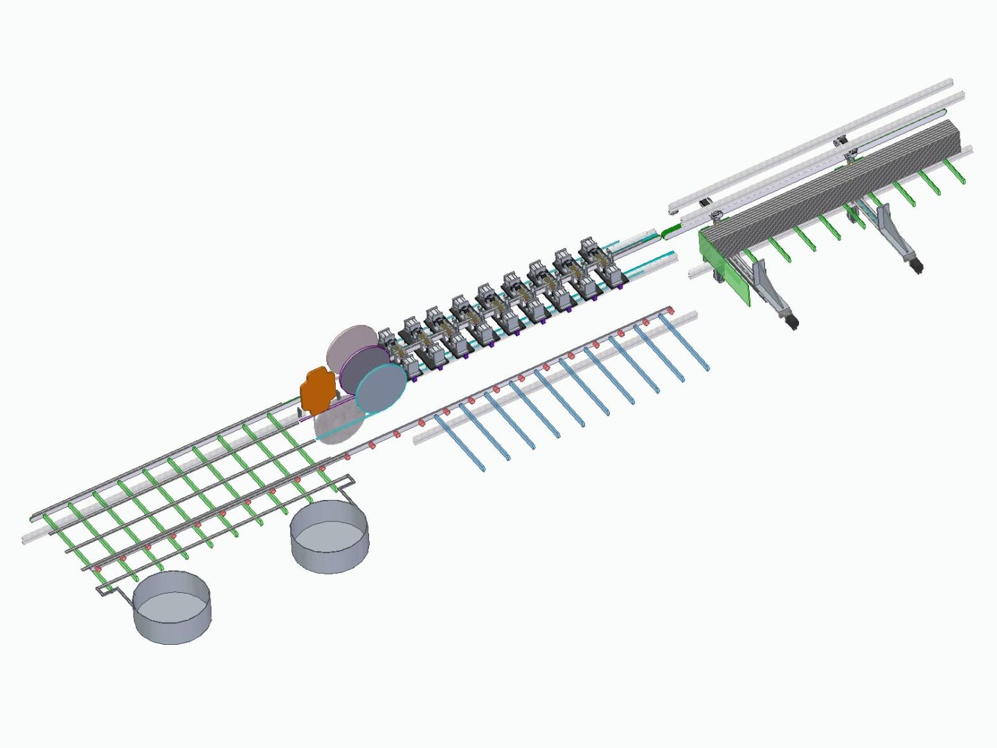
Line for production of heavy-duty cardboard Euro-pallets
Specification of the cardboard pallets production line
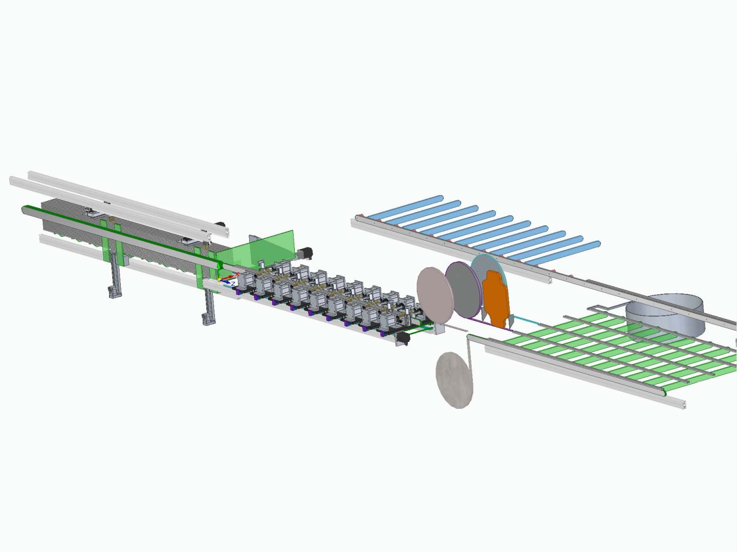
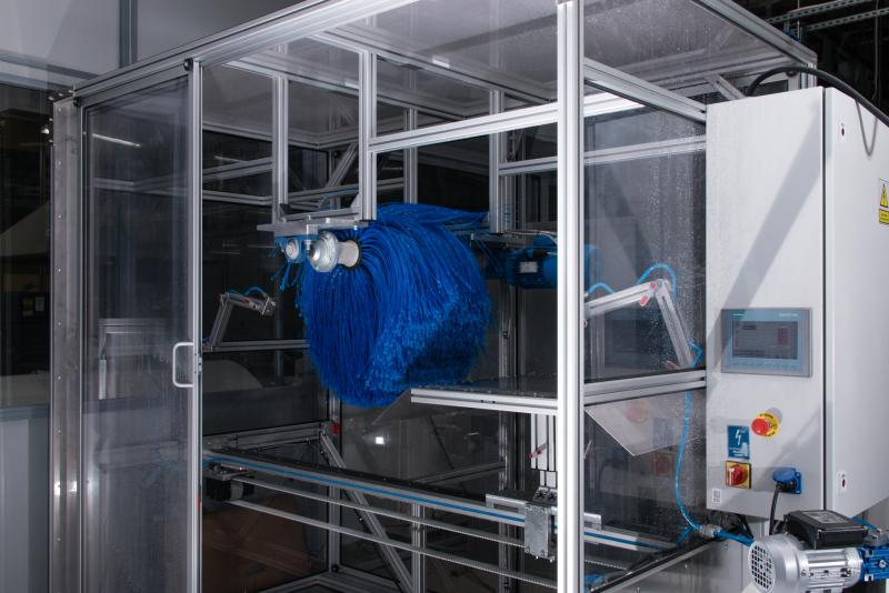
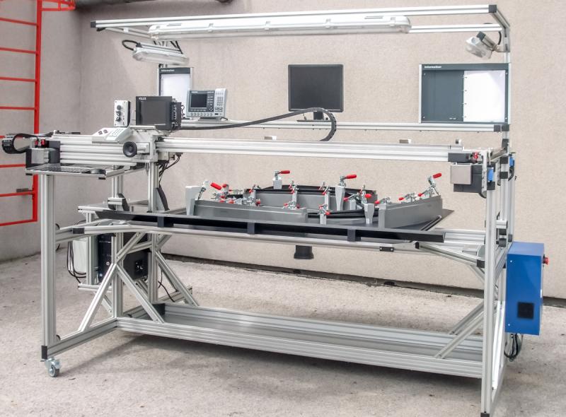
The line consists of four workstations of the following characteristics:
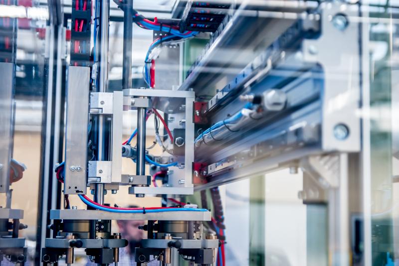
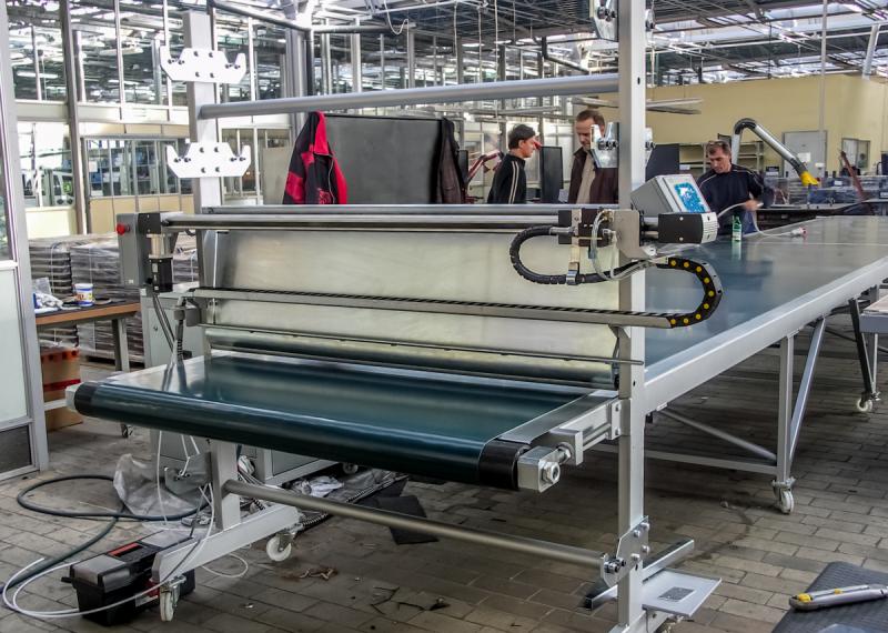
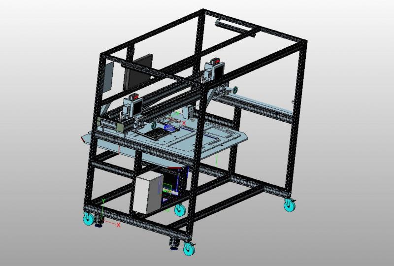
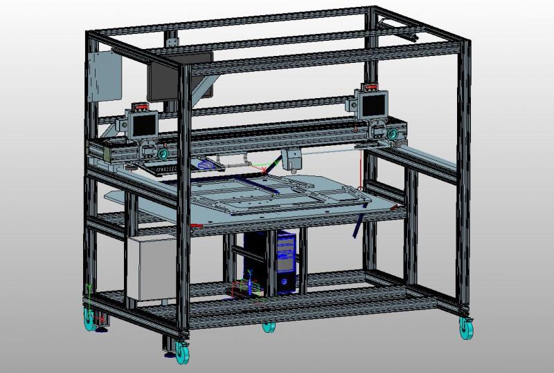
- constructed from aluminium profiles,
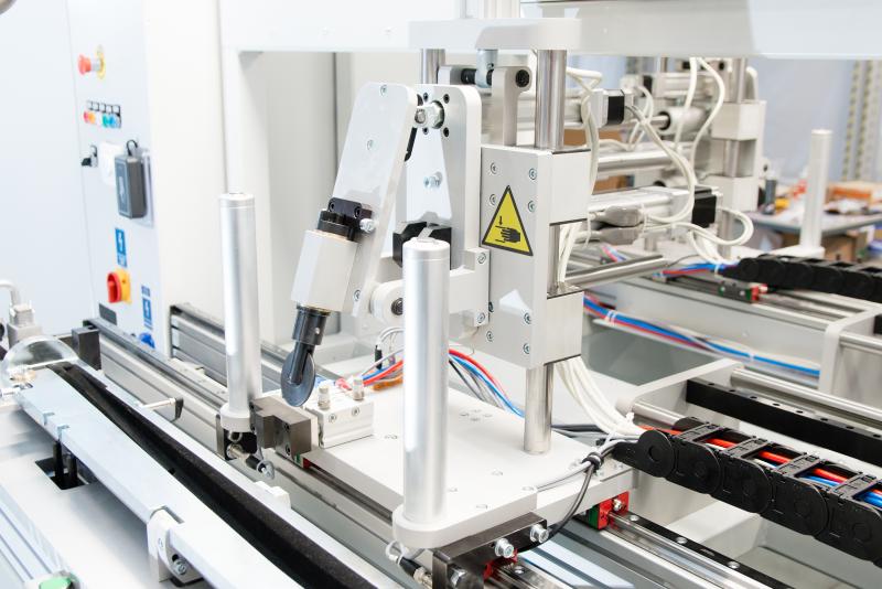
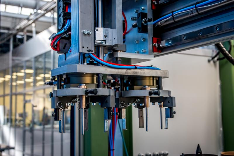
- systems of pneumatic and electric cylinders and screw mechanisms for production operations to be performed in the stations,
- mechanism for transporting parts between stations,
- component storage area,
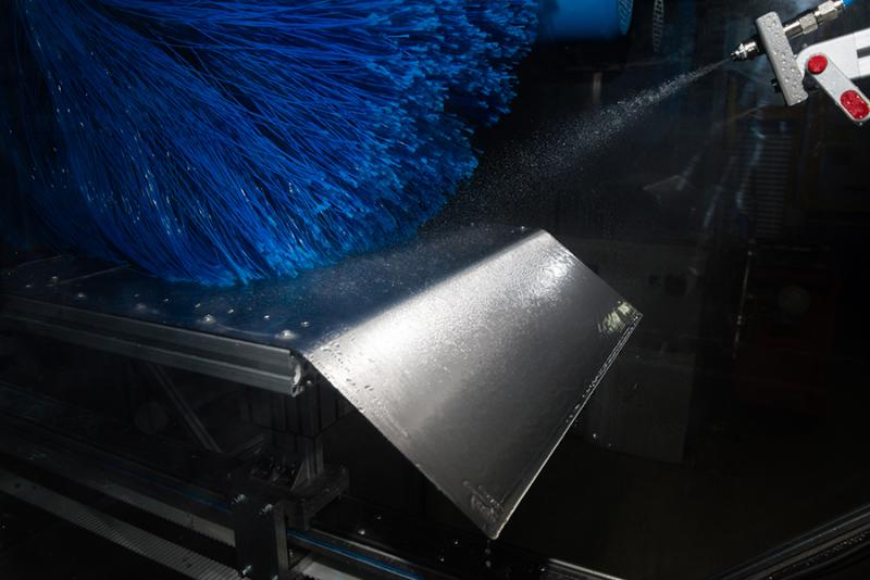
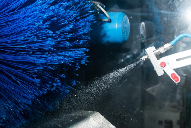
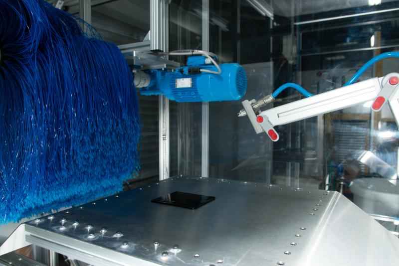
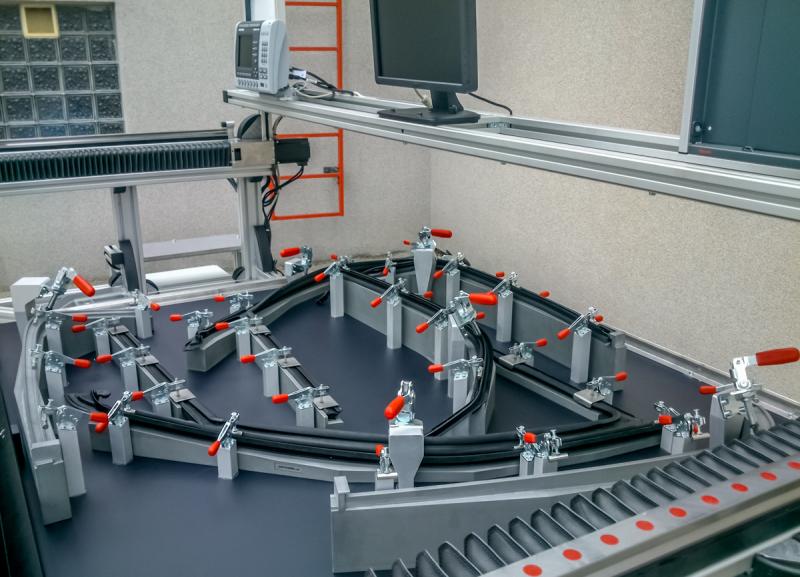
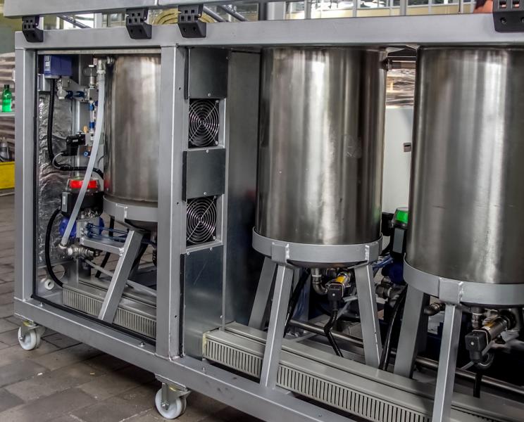
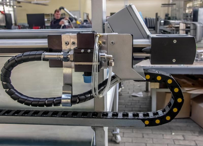
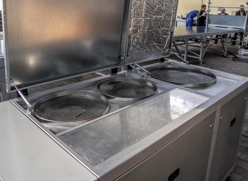
- gluing system with moving heads,
- two Cartesian coordinate systems,
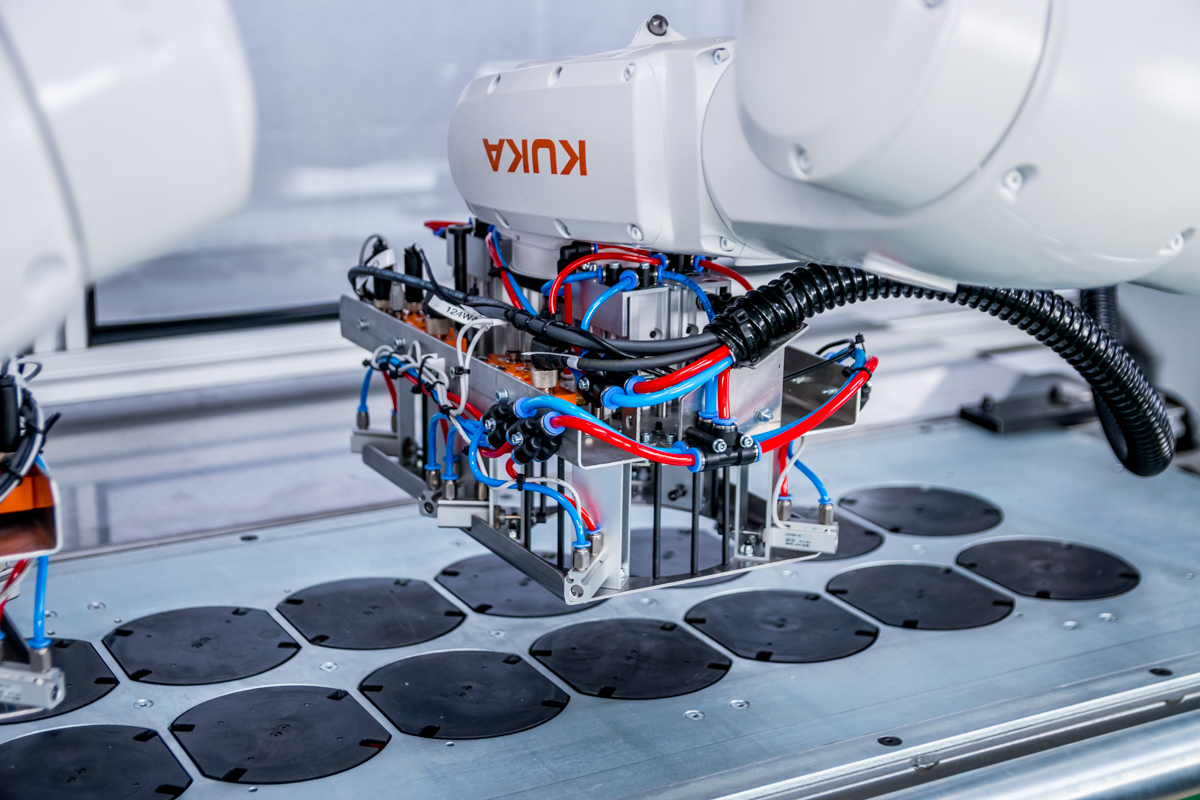
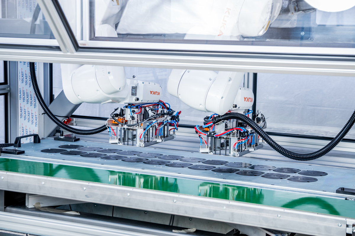
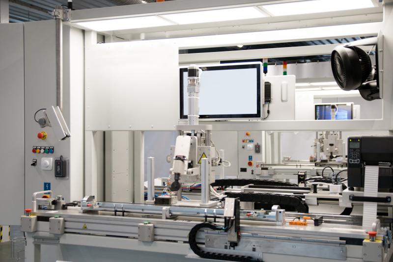
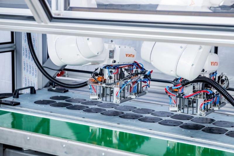
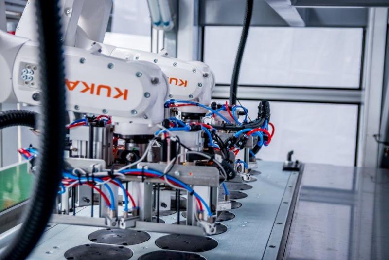
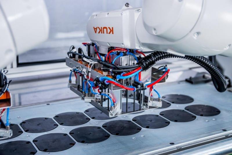
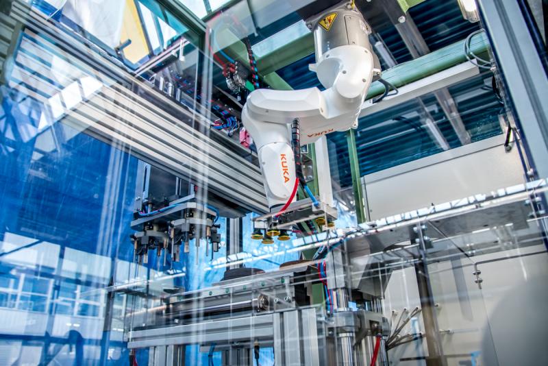
- 6-axis robot,
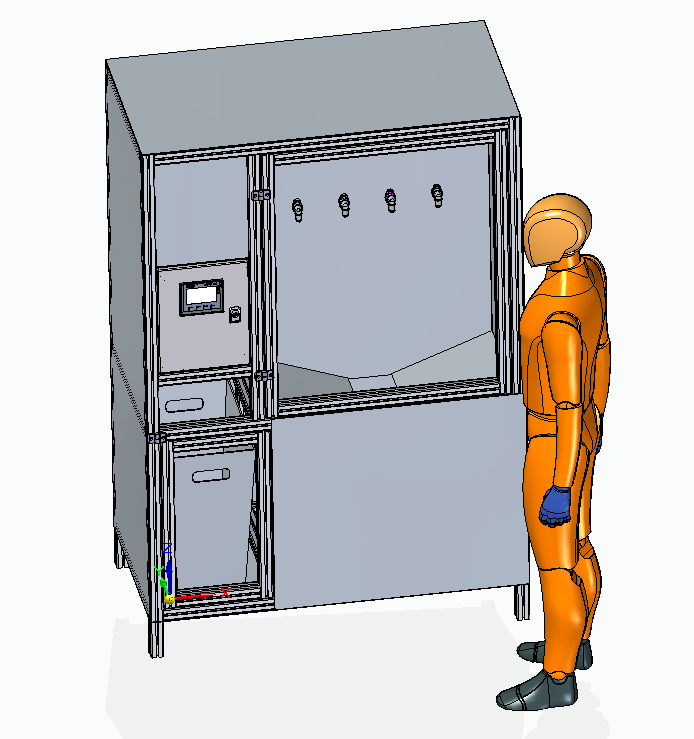
- control cabinet.
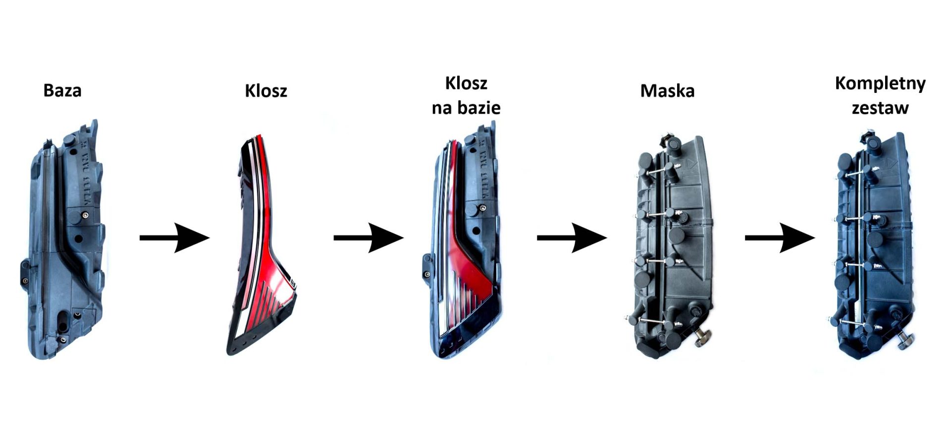
The primary function of the line is to produce cardboard tops/bottoms by folding, connecting and gluing cardboard angles, sticking board sheets, fitting reinforcements for the top and bottom and putting them on a roll conveyor. The second function is to glue short sides.
Top/bottom sizes handled: from 600×800 mm to 2200×3000 mm, with the option of smooth size changes. Sizes of short sides handled: from 580 to 2180 mm and from 500 to 2200 mm.
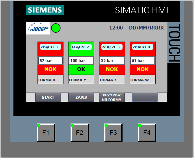
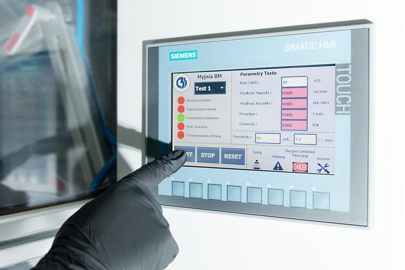
The operator’s involvement is limited to setting the line operation parameters and to manual replenishment of the storage area with components and adhesive tape rolls.
Replenishment of storage areas with components (cardboard strips, tops/bottoms, reinforcements) is achieved without interrupting operation of the line. Changing the paper adhesive tape requires interruption of line operation.
Anticipated run sequence
- Collecting cardboard strips from the storage area, folding, connecting and gluing them with paper adhesive tape at the joint (station 1)
- Gluing cardboard corners with adhesive tape (station 2)
- Applying a layer of glue, collecting top/bottom from the storage area using a manipulator and placing it on the strips covered with glue (station 3)
- Collecting reinforcement from the storage area using a robot, applying a line of glue and placing it where the strips are joined, storing the finished in the storage area using a manipulator (station 4)
- Collecting angle boards for the short sides from the storage areas, applying a layer of glue, collecting the bottom board using a manipulator and sticking the elements together (station 3)
- Storing the finished item in the storage area using a manipulator (station 4)
- Stacking finished items (next to station 4) of up to 1800 mm on a roll conveyor, automatic shifting of the stack to the side in order to make room for another stack.
- The cycle is repeated alternately until the whole programmed production process has been carried out.
Additional information
- Equipment control provided by Siemens S7-1500
- Air service unit, pneumatic cylinders and other pneumatics-related components based on SMC solutions
- Components’ accuracy ensured by screw mechanisms and electric actuators
- Parameter setting for glue lines of angle boards ensured by moving gluing heads and by a robot for reinforcement of joints
- Transport unit between stations based on a belt with integrated pushing elements
- Finished goods labelled and placed in the storage area next to station 4
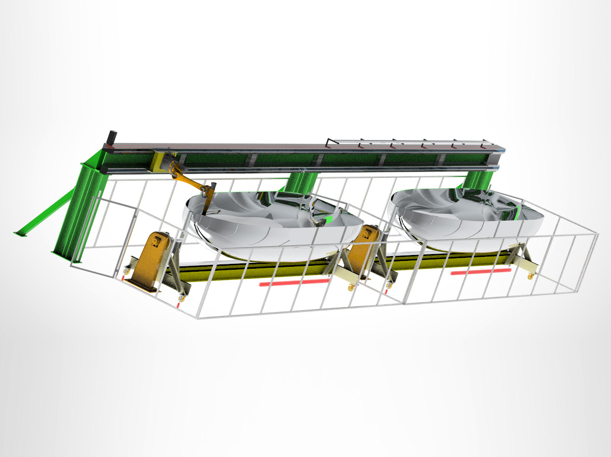
- The line complies with applicable safety requirements
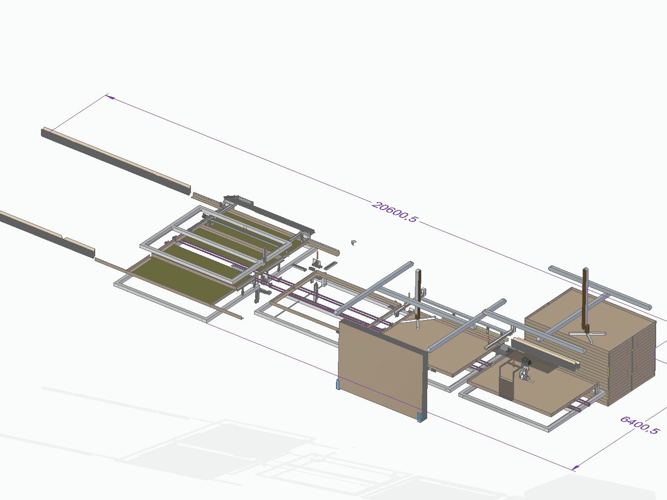
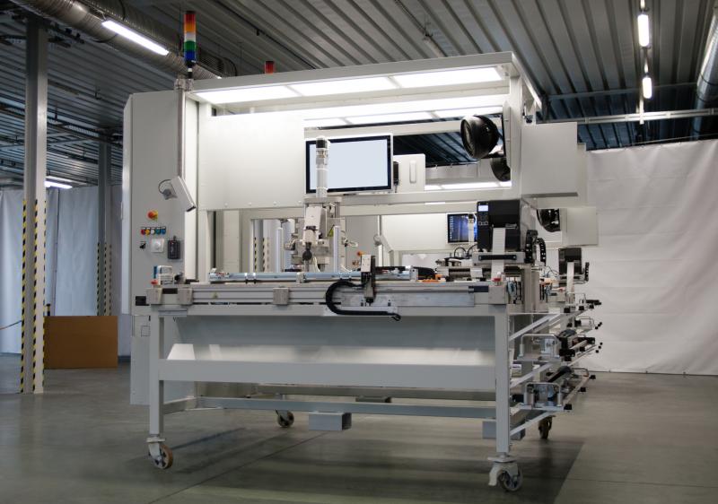
- Overall dimensions of the equipment (including protective fencing) amount to approx. 20600×6400 mm (L×W). Protective fencing installed around four sides of the line
- The system on offer includes software for one layout configuration of the angle boards inside the packaging
- Stations labelled with riveted nameplates.