Menu Decorator

Production automation. Design and production of special machines and control and measurement devices

Go back to the list

On this page:

  • Production automation. Design and production of special machines and control and measurement devices
  • Examples of design and implementations of special machines and control and measurement devices
    • Device used for lens metallising process
    • Station for automatic collection of cut-out disks from a hydraulic press
    • Station for automating the lamination process of the hulls of yachts, boats and sailing dinghies
    • Station for soaking fibreglass mats
    • Portable station for measuring surface wear of the grinding table and rolls of the vertical mill for cement grinding
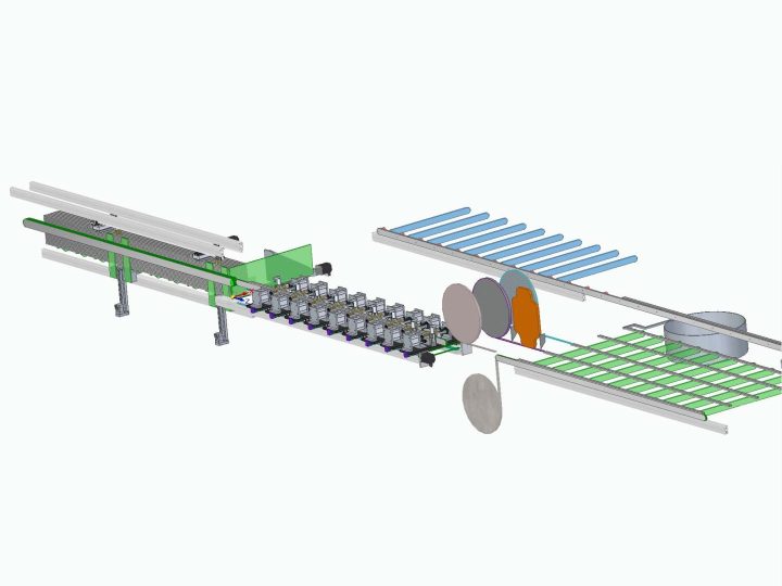
    • Line for the manufacture of indoor and outdoor doormat systems
    • Stand for testing the welding force of quick couplings of hydraulic, cooling, heating, and intake air systems
    • Line for production of heavy-duty cardboard Euro-pallets
  • Other examples
    • Laboratory car wash – simulation of conditions in an automatic car wash
    • Station for assembly, and then checking the correctness and completeness of assembly of the finished product
    • Station for automatic collection of components
    • Station for automatic receipt and separation of components
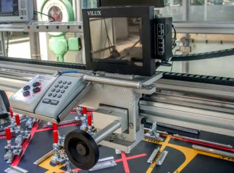
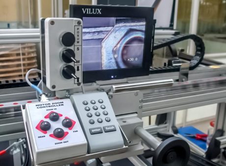
    • Device for performing optical measurements on seals
    • Device for the impregnation of textiles
    • An example of a design for a control and measurement device

Production automation. Design and production of special machines and control and measurement devices

BOSMAL deals with the design and production of:

  • special machines
  • industrial automation equipment
  • industrial prototypes
  • control and measurement equipment

applicable in various industries. We provide services across the full range, from the design stage to the production of the device or machine. Our team of designers specialises in – among other fields – pneumatics, vacuum technology, use of robots and control.
Machines are manufactured in accordance with the latest applicable EU requirements, thus allowing their use in the EU.

Examples of design and implementations of special machines and control and measurement devices

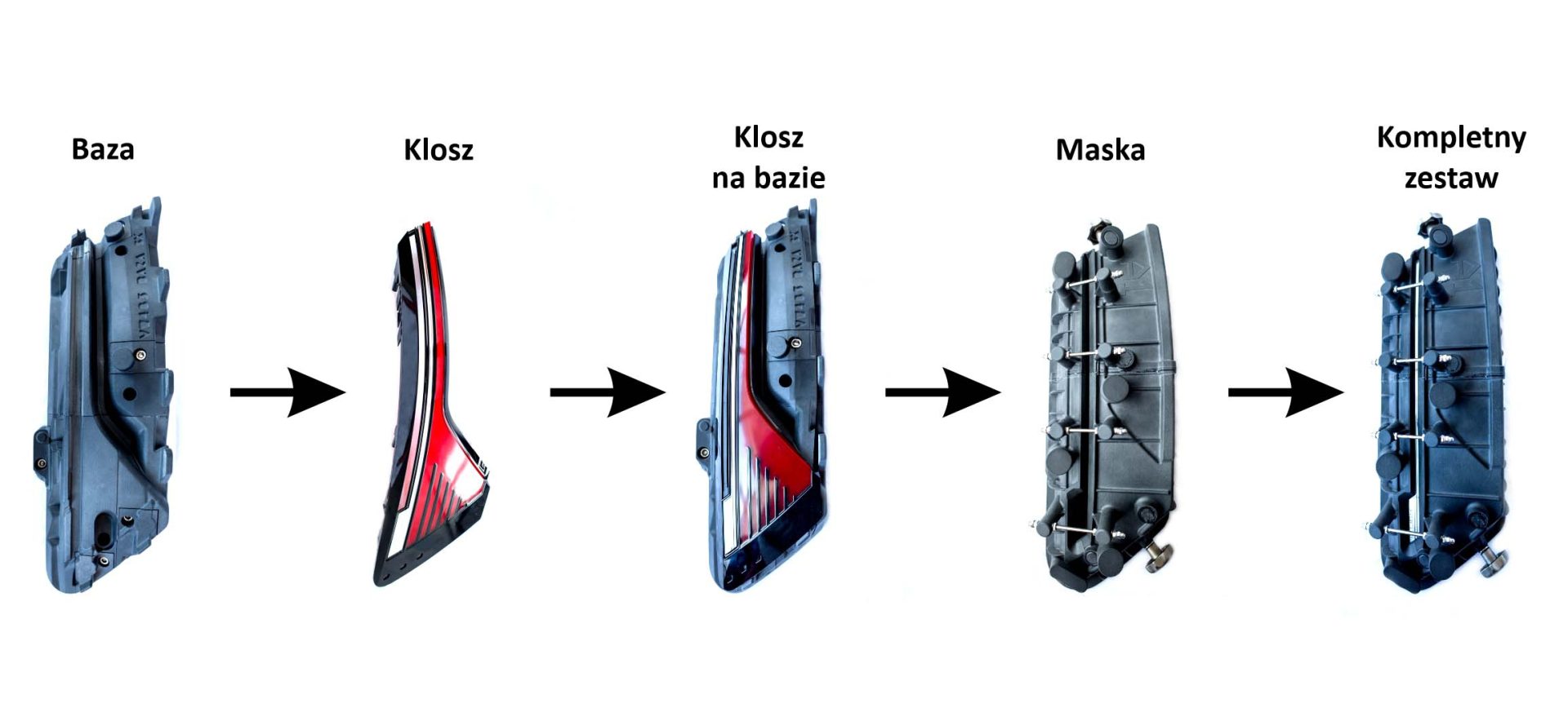
Device used for lens metalizing process

  • Short change-over times (easy and quick assembly and disassembly of mask and lens)
  • Construction technology – 3D printing
  • Use of positioning magnets facilitating precise set-up and connection of mask and base
  • Short change-over times (easy and quick assembly and disassembly of mask and lens)
  • Positioning of the mask onto the base – special positioning fixture
  • Regulated mask gap width
  • Low weight: 1.6 kg
  • Temperature resistant during operation of the paint conveyor
  • ±0.3% accuracy, with a lower limit of ±0.2 mm
  • Short implementation time for the modified device (due to 3D printing)
  • NaOH resistant (concentration of 20% at a temperature of 43°C)

Legend: for drawing

  • Baza – Base
  • Klosz – Lens
  • Klosz na bazie – Base-mounted lens
  • Maska – mask
  • Kompletny zestaw – Complete set

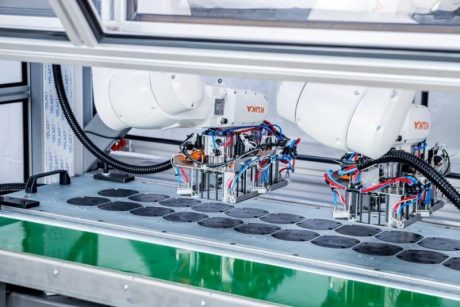
Station for automatic collection of cut-out disks from a hydraulic press

Station description

  • fixed station
  • main body made of steel, welded profiles
  • operator’s panel
  • work process signal and safety buttons
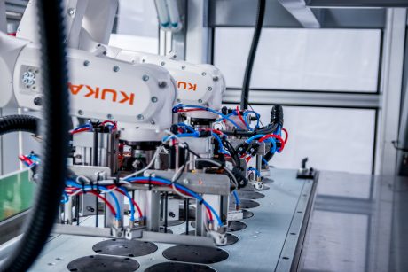
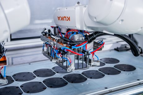
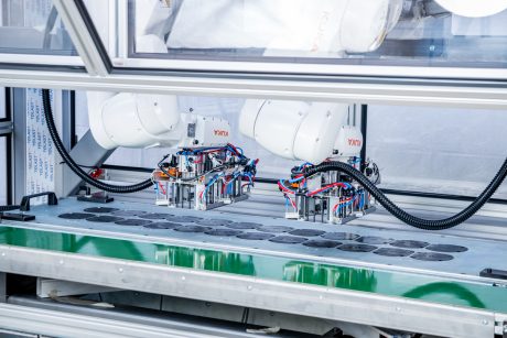
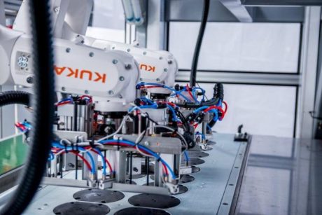
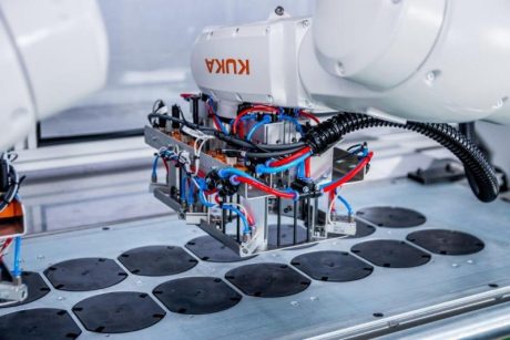
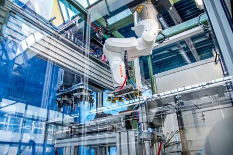
  • collection of parts performed by two KUKA 6-axis robots
  • conveyor belt
  • station consisting of the rewinder, which rewinds the sheet with cut-out discs
  • station equipped with a paper sheet tensioner
  • changeover elements equipped with handles facilitating changeover
  • quick tooling changeover
  • upper part of the station, adjustable on two axes in the range of approx. 200 mm for precise positioning following changeover
  • station equipped with SMC pneumatic elements and Siemens control elements
  • station equipped with two control cabinets

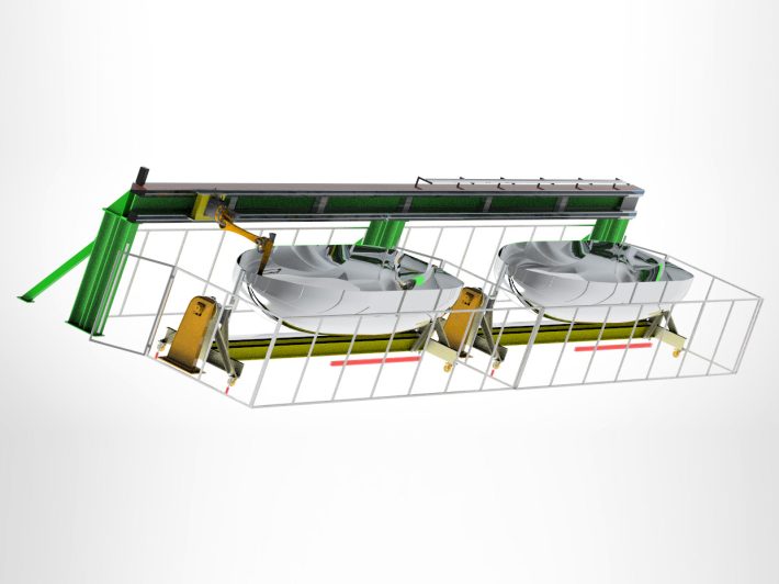
Station for automating the lamination process of the hulls of yachts, boats and sailing dinghies

Basic equipment

  • 6-axis robot
  • Guideway with dust covers
  • Steel supporting structure of the guideway, with a robot
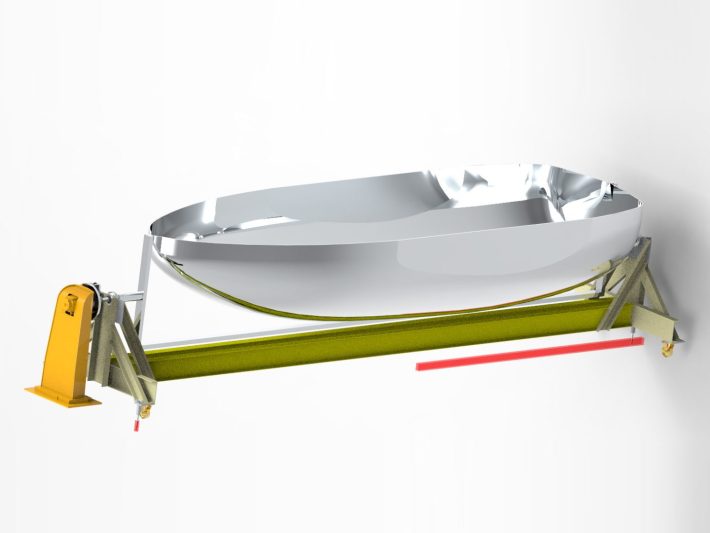
  • Two axial positioners with coupling mechanism of the hull transport cart
  • Control cabinet
  • Tools for resin coating and rolling including head with strain gauge and roller
  • Protective fencing of 4.5×23×2 m size, with sliding gate and three doors
  • Openings and rails positioning the hull transport cart in the appropriate place

Characteristics

  • The basic functionality of the equipment is rolling of the soaked fibreglass with a tool attached to the robot’s arm
  • The equipment is constructed in a way that enables manual work in parallel with the operation of the robot (in a separate area)
  • The station is manually equipped with lamination moulds
  • Positioners are on an additional robot axis, which enables access to difficult-to-reach places, maintaining the required process parameters (tool rake angle, clamp, etc.)
  • Device control provided by Siemens S7-1500
  • Air service unit, pneumatic valves and other pneumatics-related components based on SMC solutions
  • Complies with safety requirements regarding operation in an explosion hazard zone – zone no. 2
  • Overall dimensions of the equipment (including protective fencing) amount to approx. 4.5×23×4 m

Suggested run sequence

  • Pre-soaking of the hull area 1 by employees
  • Rolling of the pre-soaked hull area 1 by the robot, pre-soaking of hull area 2 by employees
  • Rolling of the pre-soaked hull area 2 by the robot, pre-soaking of hull area 1 by employees
  • The cycle is repeated alternately until the whole programmed area of the hull has been treated

Optional functionality of the equipment as per a separate appraisal

  • Resin and hardener spray
  • Gel coat spray
  • Fibreglass, resin and hardener spray

Station for soaking fibreglass mats

Characteristics

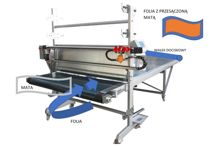
The basic function of the equipment is to soak the fibreglass mat, cut to a specific size, with resin mixed with hardener and to roll the resin with rollers.

The device is constructed in a way that enables soaking with the use of conveyor belt in operation.

Suggested run sequence:

  • Selection of the operational parameters by the operator
  • Feeding fibreglass mat, cut to a specific size, and foil onto the conveyor belt
  • Soaking the mat by pouring resin and hardener over it and passing it through the roller assembly

Complies with safety requirements regarding operation in an explosion hazard zone – zone no. 2.

Overall dimensions of the equipment (including protective fencing) amount to approx. 5.5×2.5×1.8 m

Basic equipment

  • Movable axle with mixed resin pouring head
  • Conveyor belt transporting fibreglass mat
  • Hydraulic system feeding resin and hardener
  • Rollers assembly for mat soaking
  • Resin and hardener tanks
  • Station for foil and fibreglass mat rolls
  • Supporting structure with driving wheels
  • Control cabinet, operator’s panel

Legend for drawing:

  • Folia z przesączoną matą: foil with soaked mat
  • Wałek dociskowy: pressure roller
  • Mata: mat
  • Folia: foil

Portable station for measuring surface wear of the grinding table and rolls of the vertical mill for cement grinding

Basic equipment

  • Main frame with driving slideway with a range of approx. 1300 mm
  • Laser distance sensor
  • Removable digital protractor
  • Replaceable stands – 2 pcs:
    • for grinding table – 1 pc
    • for rolls – 1 pc
  • Stands with the option of inclination angle adjustment of the sensor in relation to the surface to be measured (height adjustment of one of the stand legs)
  • Instrument case of approx. size 1500×800×500 mm
  • Electrical control box with PLC inside the case
  • Carrier handles.

Instrument assembly

  • For grinding table measurement – in the fixed base on one side, gravitationally inside the grinding table on the other side; fixed base welded to the grinding mill structure in front of the inspection point
  • For roll measurement – in the fixed bases on one side, gravitationally on the roll frame; fixed bases with the use of threaded holes for the sleeves mounted on the roll surface area.

Measurement procedure

  • Setting the appropriate inclination angle of the sensor in relation to the surface to be measured by means of a magnetic digital protractor
  • Laser distance sensor performing spot measurement along the cross-section of the working surface of the grinding table and roll
  • Uploading measurement results to the data carrier (SD card or USB mass storage device)
  • Possibility of measuring the working surface of the grinding table in four points (every 90 degrees or to be decided following order receipt), mechanical rotation of the grinding table
  • Possibility of measuring working surface of the rolls in four points (every 90 degrees or to be decided following order receipt), manual rotation of the roll
  • Measurement result readout every 10 mm (or at another value, to be specified).

Line for the manufacture of indoor and outdoor doormat systems

Characteristics

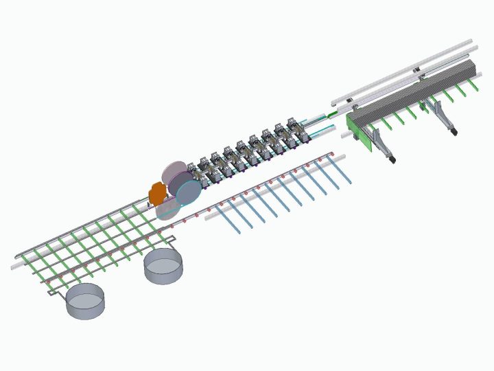
The basic function of the line is the manufacture of doormat systems consisting, of preparing aluminium profiles and installing strips of matting compatible with the profile.

The operator’s involvement is limited to setting line operation parameters and replenishing the storage area with components.

Anticipated run process:

  • setting production parameters for a given type of doormat system (by the operator)
  • collecting the profile from the storage area and transporting it to the punching station with set parameters
  • transportation to the next station, where the profile is glued by rubber tape
  • transportation to the next station, where the profile is equipped with doormat inserts
  • inserting plastic plugs into the ends of the profiles
  • transportation to the final storage area

Equipment control provided by Siemens
Air service unit, pneumatic cylinders and other pneumatics-related components based on SMC solutions

Overall dimensions of the equipment including protective fencing amount to approx. 11300×2700×1600 mm.

Elements of five workstations

  • Systems of pneumatic and electrical cylinders, screw mechanisms for production operations to be performed in the stations
  • Constructed from alminium profiles
  • Mechanism for transporting parts between stations
  • Component storage area
  • Control cabinet and tooling

Station functionality

  • S1 – Feeding the line with charge material consisting of aluminium profiles
  • S2 – Making the holes to connect the profiles and create the doormat module
  • S3 – Profile being glued by rubber tape and installing doormat inserts
  • S4 – Sealing the external gaps (profile ends) with plastic plugs
  • S5 – Transporting ready product to the storage area for final assembly

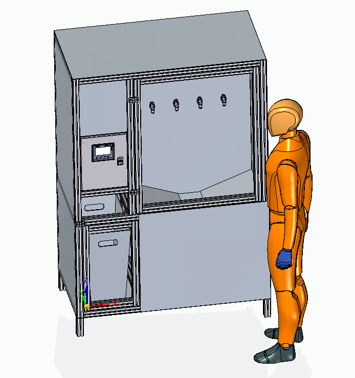
Stand for testing welding force of quick couplings of hydraulic, cooling, heating, and intake air systems

Functions of the stand for testing welding force of PS3 type connectors

  • Hydraulic system, after turning the power off, drops all the pressure to the overflow tank
  • Stand is equipped with a hydraulic power unit with a safety overflow for 110 bar
  • For each tested connector (4) there is one 2/2 shut-off valve blocking the flow when a pressure drop is detected on the tested connector
  • The test area is protected on the operator’s side by a door with a bolt lock and a safety contactor
  • The device has uniform hydraulic couplings of the tool, on which the operator puts the connectors
  • Connection is controlled by four sensors installed at the plug-in socket and by pressure sensors
  • The program carries out an automatic test cycle – the system pressure is regulated by an overflow valve in the pump supply system
  • The accuracy of the installed pressure sensors is ±0.5%, as stated in manufacturer’s documentation
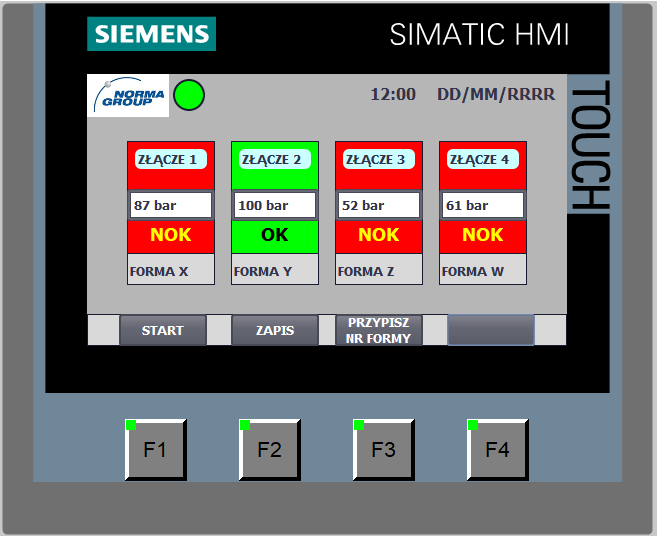
  • Before starting the tests, the operator assigns the mould socket number to the tested coupling using the operator’s panel and entering the values to the panel boxes
  • After the work cycle, the program displays the information about the test run status (pressure, coupling number, etc.) on the operator’s panel installed on the electrical cabinet door, for each of the test sockets
  • Option of test performing using fewer than four tools – based on information about the pressure and the presence of couplings, the channels supplying the working medium to unused tools are cut off
  • Test results are archived in form of a file (.csv or .txt) on USB mass storage device for each tool
  • Worn-out connectors isolated after the test with a meter based on a laser sensor in the inlet to the protected zone
  • Target working medium: propylene glycol

Basic equipment

  • Hydraulic unit with pressure up to 100 bar
  • Hydraulic system with pressure distributors and transducers for control
  • Operation control unit
  • Aluminium frame made of construction profiles with external covers
  • Overflow tank for the working medium
  • A set of technological connections for given types of connectors

Specification

  • The basic functionality of the device is testing the breaking pressure of connectors’ welded rings
  • Overall dimensions of the equipment amount to approx. 1×0.68×1.65m
  • Station labelled with riveted nameplate.

Suggested run time

  • Equipping the connectors with hydraulic fittings on the device
  • Assigning socket number to the tested connector
  • Starting the pump and gradual pressure increase
  • Changing valves position when a pressure change is detected as a result of unsealing
  • Pressure release from the system within 1 minute of the test finishing
  • Providing information about the end of measurements and presenting test results

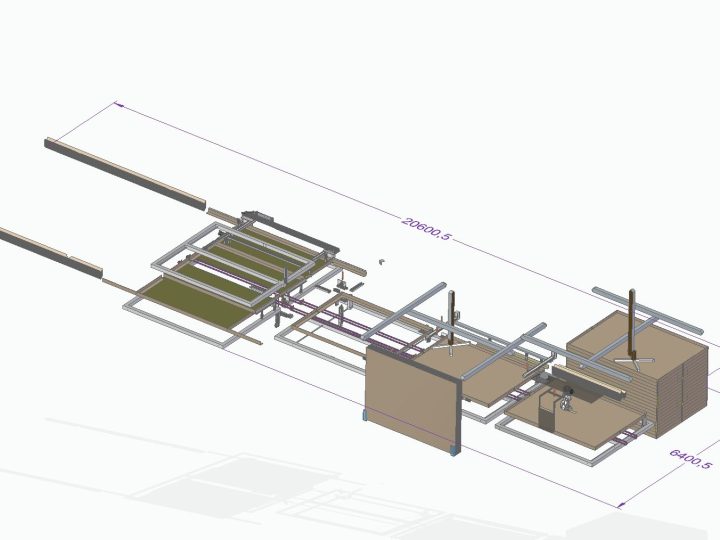
Line for production of heavy-duty cardboard Euro-pallets

Specification of the cardboard pallets production line

The line consists of four workstations of the following characteristics:

  • constructed from aluminium profiles,
  • systems of pneumatic and electric cylinders and screw mechanisms for production operations to be performed in the stations,
  • mechanism for transporting parts between stations,
  • component storage area,
  • gluing system with moving heads,
  • two Cartesian coordinate systems,
  • 6-axis robot,
  • control cabinet.

The primary function of the line is to produce cardboard tops/bottoms by folding, connecting and gluing cardboard angles, sticking board sheets, fitting reinforcements for the top and bottom and putting them on a roll conveyor. The second function is to glue short sides.

Top/bottom sizes handled: from 600×800 mm to 2200×3000 mm, with the option of smooth size changes. Sizes of short sides handled: from 580 to 2180 mm and from 500 to 2200 mm.

The operator’s involvement is limited to setting the line operation parameters and to manual replenishment of the storage area with components and adhesive tape rolls.

Replenishment of storage areas with components (cardboard strips, tops/bottoms, reinforcements) is achieved without interrupting operation of the line. Changing the paper adhesive tape requires interruption of line operation.

Anticipated run sequence

  • Collecting cardboard strips from the storage area, folding, connecting and gluing them with paper adhesive tape at the joint (station 1)
  • Gluing cardboard corners with adhesive tape (station 2)
  • Applying a layer of glue, collecting top/bottom from the storage area using a manipulator and placing it on the strips covered with glue (station 3)
  • Collecting reinforcement from the storage area using a robot, applying a line of glue and placing it where the strips are joined, storing the finished in the storage area using a manipulator (station 4)
  • Collecting angle boards for the short sides from the storage areas, applying a layer of glue, collecting the bottom board using a manipulator and sticking the elements together (station 3)
  • Storing the finished item in the storage area using a manipulator (station 4)
  • Stacking finished items (next to station 4) of up to 1800 mm on a roll conveyor, automatic shifting of the stack to the side in order to make room for another stack.
  • The cycle is repeated alternately until the whole programmed production process has been carried out.

Additional information

  • Equipment control provided by Siemens S7-1500
  • Air service unit, pneumatic cylinders and other pneumatics-related components based on SMC solutions
  • Components’ accuracy ensured by screw mechanisms and electric actuators
  • Parameter setting for glue lines of angle boards ensured by moving gluing heads and by a robot for reinforcement of joints
  • Transport unit between stations based on a belt with integrated pushing elements
  • Finished goods labelled and placed in the storage area next to station 4
  • The line complies with applicable safety requirements
  • Overall dimensions of the equipment (including protective fencing) amount to approx. 20600×6400 mm (L×W). Protective fencing installed around four sides of the line
  • The system on offer includes software for one layout configuration of the angle boards inside the packaging
  • Stations labelled with riveted nameplates.

Other examples

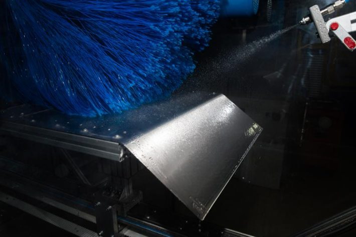
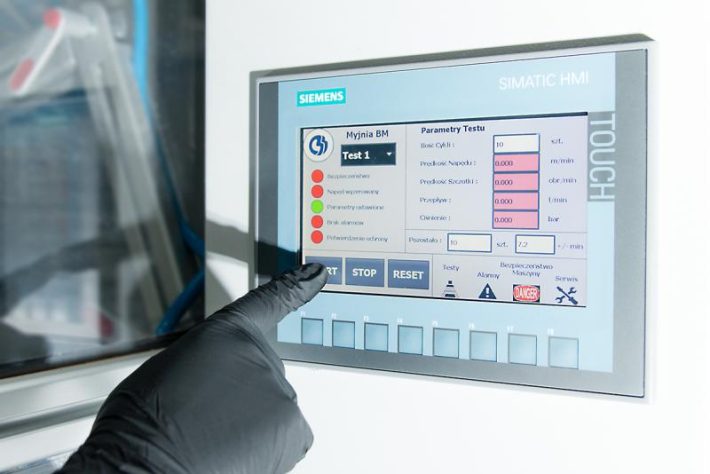
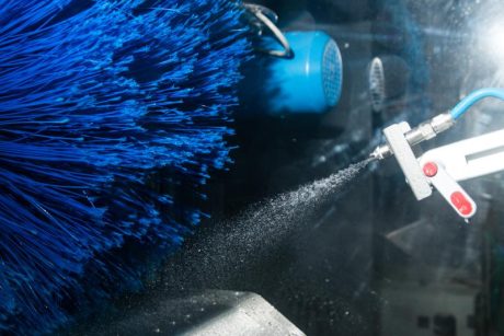
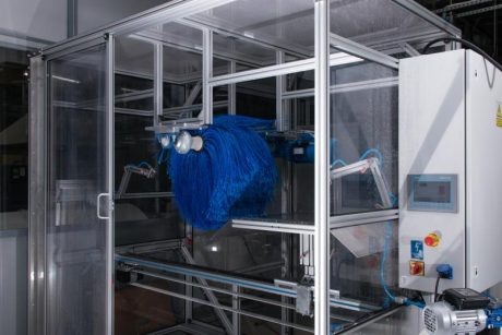
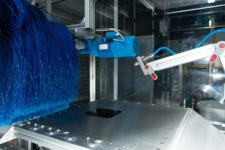
Laboratory car wash – simulation of conditions in an automatic car wash

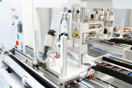
Station for assembling and then checking the correctness and completeness of assembly of the finished product

Station for automatic collection of components

Station for automatic receipt and separation of components

Device for performing optical measurements on seals

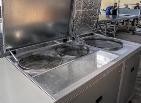
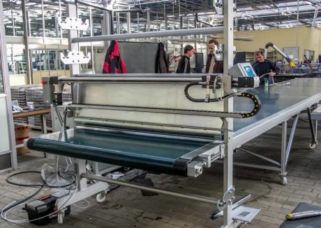
Device for the impregnation of textiles

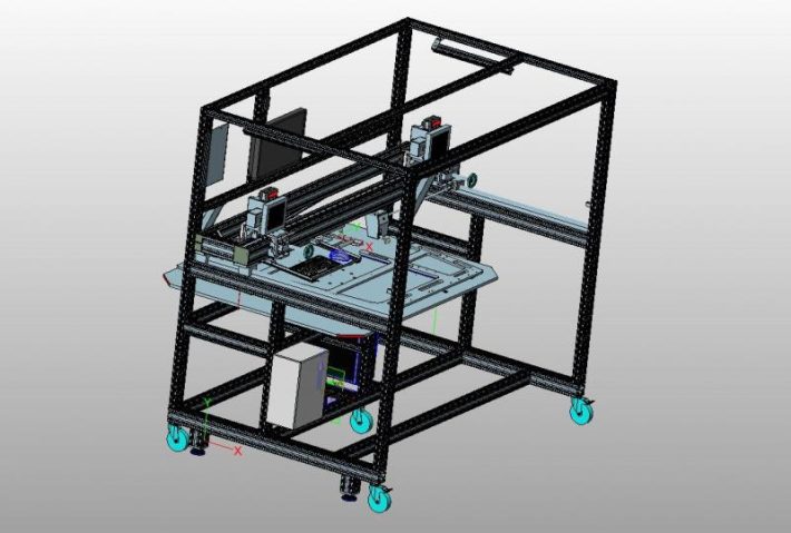
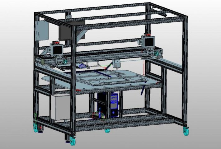
An example of a design for a control and measurement device


Back
to top